カー オーディオの電気理論 – キャパシタンスとインダクタンス
 カー オーディオの電気理論の議論が終わりに近づくにつれ、静電容量とインダクタンス、およびその方法について説明する必要があります。これらの現象の特性は、AC および DC 信号と相互作用します。これらが高度な概念であることは疑いの余地がありませんが、コンデンサとインダクタがどのように機能するかについての基本的な理解でさえ、モバイル エレクトロニクス システムを完全に理解するための基礎となります。
コンデンサとは?
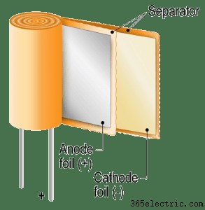 コンデンサは、エネルギーを蓄える 2 端子の電子部品です。コンデンサは、電気絶縁体によって分離された 2 つの金属板でできています。コンデンサの一方の端子に電圧を印加すると、一方のプレート上の電子が反対側のプレートに力を加えて反対の電荷を生成します。その結果、プレートは等しく反対の電荷を持つため、電界が維持されます。コンデンサーの極板は互いに非常に接近しているため、全体のサイズに対して大量のエネルギーを蓄えることができます。
コンデンサはファラッドの単位で定量化されます。ファラッドは、各プレートの 1 クーロンの電荷として定義され、端子間に 1 ボルトの電圧が発生します。
Capacitors in DC Circuits
 Capacitors are, at their most basic function, a device that stores a microscopic magnetic field between its plates. When we apply a DC voltage to a discharged capacitor, it appears as a short circuit for an instant as the magnetic and electric fields start to form between its plates. As the capacitor starts to store energy, it increases in effective resistance, and the amount of current flowing through the device is reduced. Once the capacitor has equalized with the supply voltage, almost no current passes through the device.
When we remove the supply voltage from a capacitor, it will attempt to maintain the voltage across the terminals. It is this characteristic that makes capacitors an ideal solution to reduce variations in voltage. Capacitors resist changes in voltage.
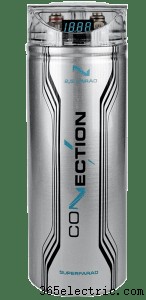
Inside the amplifiers in our car audio systems, capacitors are used to store large amounts of energy at the rail voltage. When there is a sudden demand for current that exceeds the capability of the power supply, the capacitors will release energy to maintain their initial voltage. This characteristic helps to stabilize the voltage of the amp during dynamic transients. This same concept applies to “stiffening capacitors” used on the 12V feed to your amplifier. When implemented using high-quality components, the addition of a large capacitor can help to provide transient current to the amp.
The Capacitor in AC circuits
 In alternating current circuits, capacitors take on an interesting phenomenon of “virtual resistance.” As we know, capacitors don’t like to change voltage, yet an AC signal is one that is defined as ever-changing. Depending on the relationship between the capacitor value and the frequency of the AC signal, some amount of the current is allowed to pass through the cap.
If we attempt to measure the resistance of a capacitor with a conventional multimeter, we’ll find it shows an extremely high value. For AC signals, we use the formula Xc =1 / (2 x 3.1416 x F x C) to calculate the effective resistance, where F is the frequency of the signal and the C is the value of the capacitor in farads. Because this resistance is not present in DC signals, we call it capacitive reactance.
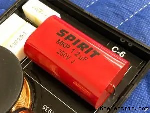
If we wanted to create a simple filter circuit to limit the amount of low-frequency signal going to a speaker, we could wire a non-polarized capacitor in series with the speaker. To calculate the frequency at which the cap starts to reduce bass going to the speaker, we can rearrange the above equation to F =1 / (2 x 3.1416 x R x C), where R is the same value as the speaker resistance. For a four-ohm speaker and a capacitor with a value of 200 uF (microfarads), we get a frequency of 198.9 Hz. At this frequency, the capacitor appears to have the same reactance as the speaker, and the signal that is going to the speaker is reduced by 50 percent. Because capacitance is inversely proportional to frequency, the impedance of the capacitor increases as frequency decreases. At 99 Hz, the reactance is 8 ohms, at 50 Hz, it’s 16 ohms, and so on. This phenomenon simultaneously reduces the current supplied by the amplifier and acts as a voltage divider between the cap and the speaker.
A capacitor in series with a speaker is known as a first-order high-pass filter. It reduces the output of the speaker at a rate of -6dB per octave as you move away from the crossover frequency as defined above. Capacitors are suitable as filters for midrange and high-frequency drivers in passive designs and as protection devices for tweeters in active designs.
What Is an Inductor?
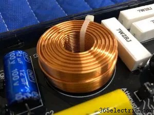
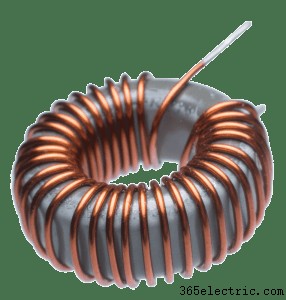 In the simplest of terms, an inductor is a coil of wire that creates a magnetic field based on the amount of current flowing through it. Many inductors feature iron cores to increase the intensity of the magnetic field. Where a capacitor resists changes in voltage, an inductor resists changes in current flow. We know from our previous article on magnetism that current flowing through a conductor creates a magnetic field around that conductor. If we wrap the conductor in a loop, the proximity of the loops to one another intensifies the magnetic field.
Also from our previous article, we also know that a magnetic field can impose a voltage on a conductor. If the current in an inductor tries to change, the magnetic field attempts to create a voltage across the device to maintain the current flow.
A good analogy for an inductor is a flywheel on a motor. Once you have established a specific rotational speed, it takes a large amount of work to increase or decrease its speed. Inductors work the same way with current. They resist changes in current flow. Inductors are rated using the unit henry (H). A henry is defined as the opposition to electrical current flow through a device that results in one volt of electromotive force to appear across the terminals.
Inductors in Electrical Circuits
 In most applications, we don’t want inductors in a 12V DC circuit because they resist changes in current flow. For a variable load such as an amplifier, a large amount of inductance in the supply wiring would result in an unstable supply voltage as the current requirements change.
There are some cases where inductors are used in combination with a capacitor to act as a noise filter.
In an AC circuit, inductors allow low-frequency signals to pass through the device with little to no effect. If we wire an inductor in series with a speaker, it acts as a high-pass filter. Unlike a capacitor, in a DC circuit, an inductor appears as a short circuit with very little resistance. To an AC signal, we can calculate the reactive inductance of a capacitor using the equation Xl =1 x 3.1416 x F x L, where F is frequency and L is inductance in henries.
If we want to use an inductor as a high-pass filter, we can determine the effective crossover point by swapping the Xl for the resistance of the speaker. In this example, we’ll use an inductor with a value of 6 mH (millihenries) and a speaker with a nominal impedance of 4 ohms. There, the -3dB point of the filter circuit would be F =4 / (2 x 3.1416 x 0.006), or 106.1 Hz. This value of inductor would make a good low-pass filter for a woofer. Just as with a capacitor in series with a speaker, an inductor acts as a first-order filter and reduces output at a rate of -12dB per octave as frequency increases from the crossover point.
Other Cases of Inductance and Capacitance
Anytime two conductors are parallel to each other and in close proximity, there will some level of capacitance. Many overly exuberant enthusiasts talk about capacitance in interconnect cables. While this is a factor, the microscopic changes (if indeed any are perceptible) can be compensated for during the tuning process of the system. When it comes to buying high-quality interconnects, noise rejection and overall design durability should be your top goals.
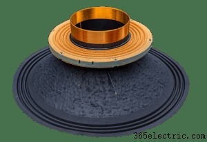
The voice coil winding in the speakers we use has a certain amount of inductance. This characteristic reduces high-frequency output by reducing current flow at high frequencies. Because speakers are dynamic, their parameters change as the speaker cone moves. In the same way that having an iron core in an inductor increases inductance as compared to an air-core design, the inductance of a speaker voice coil increases when the cone assembly moves rearward into the basket. The T-yoke in the center of the speaker increases the strength of the magnetic field created by the current in the voice coil. Likewise, as the speaker moves forward, the inductance decreases. These position-based inductance distortions can cause a high-frequency warbling effect that can be detrimental to the reproduction of your music. One solution is to implement an under-hung voice coil design where the gap is taller than the coil winding. The drawback to this design is that the voice coil is often small and lacks power handling. Another option is to include a copper pole piece cap to reduce the magnetic field and minimize distortion. A copper cap is an expensive option but offers excellent performance benefits.
Car Audio Electrical Theory
For now, this is the end of our series of articles on car audio electrical theory. We hope you’ve enjoyed learning about the physics behind how your car audio system works. Our goal is to educate enthusiasts so that they can make educated purchases and upgrades to their mobile sound system. If you have any questions, drop by your local mobile electronic specialist retailer. They can help you design an upgrade that will truly transform your commute into an enjoyable listening experience.