スピーカー クロスオーバーを設計および構築する方法 – 図付きの DIY ガイド!
ようこそ!この大きなハウツー ガイドでは、自分でデザインして構築する方法を紹介します。 スピーカー クロスオーバー 家庭用またはカー オーディオ用。
基本的なものからより高度なデザインまで、独自のデザインを数多く作成してきました。その過程で学んだことを共有したいと思います。かなりの部分をカバーするので、掘り下げていきましょう!
このハウツー ガイドの対象
パッシブ クロスオーバー デザイン タイプには非常に多くの種類とバリエーションがあるため、すべてを網羅することは現実的ではありません。物事を管理しやすくし、多くの人 (あなたと同じように!) を助けるために、スピーカー システムのニーズの 95% 以上に対応するいくつかのオプションの 1 つを構築するために知っておくべきことを説明します。
この記事がどのように役立つか
私の記事では、日曜大工 (DIY) を構築するためのノウハウ、図、情報、および手順を提供します スピーカー クロスオーバー 思い通りのサウンドを得るために 私自身の実体験に基づいています。大きな頭痛の種や破産することなく、使用して誇りに思うものを構築することは完全に可能です!
このハウツー ガイドで説明する内容:
- 1 ウェイ (ツイーターのハイパスまたはウーファーのローパス)、2 ウェイ、3 ウェイのクロスオーバー
- 使用するのに適した 1 次および 2 次クロスオーバー デザイン タイプ
- 必要なカットオフ周波数 (クロスオーバー周波数) の数値を決定する方法
- 必要に応じてダウンロードまたは印刷できる回路図を作成するのに役立ちます。
- スピーカーのインピーダンス (スピーカーのオーム) について知っておくべきことと、それが重要な理由
- 購入する適切な部品を選択し、部品の価値に対する実践的なアプローチ
- 正しいパーツの値が見つからない場合の対処法
- クロスオーバー ネットワークを配線し、すべてを組み立てます (カスタム回路基板を構築する必要はありません)。
- その追加のタッチとさらに優れたパフォーマンスのために行う追加のこと
(ここにあるアイデアに慣れていない場合は、いくつかのセクションを飛ばしてもかまいません。)
注: これはより高度な記事を意図したものではないため、ボイス コイルのインピーダンス、位相応答、音波の軸外応答、位相シフト、または 4 次設計オプションなどのいくつかの技術的側面については触れません。
パッシブ クロスオーバーはどのように機能しますか? (初心者向けの簡単なガイド)
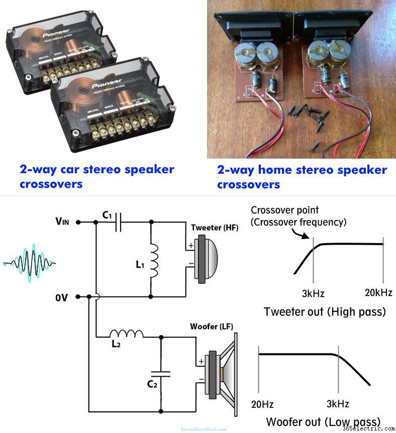
パッシブ クロスオーバー フィルターは、アクティブ クロスオーバー (電子オーディオ設計、アンプ、プリアンプなどで使用される) とは異なり、電力を供給されていないパッシブ コンポーネントを使用して周波数を除外します。スピーカーまたはスピーカーに到達する前の範囲。実際には、ステレオまたはアンプからの入力信号を大幅に低減または減衰させることにより、不要な音の周波数がスピーカー ドライバーに到達するのを効果的に「ブロック」します。
これは、リアクタンスと呼ばれるコンデンサとインダクタの特性により可能になります。リアクタンスは電流の流れに対する抵抗であり、オーディオ信号の周波数によって変化します。これにより、スピーカー端子に存在する信号レベル (スピーカーレベル電圧) の量を制御する信号へのインピーダンスが作成されます。
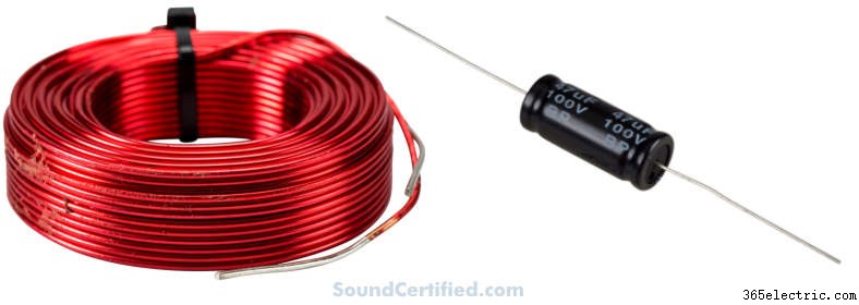
コンデンサとインダクタの役割 クロスオーバー ネットワーク デザイン
- A コンデンサ 以下の周波数では、電流の流れに対する抵抗が増加します。 クロスオーバー ポイント .これは、スピーカー負荷 (オーム負荷) と直列に接続すると、ハイパス フィルターとして機能することを意味します。
- インダクタ より高い周波数では、電気の流れに対する反対が大きくなります。 クロスオーバー ポイント . これは、スピーカーと直列に接続すると、ローパス フィルターとして機能することを意味します。
これらの実際の用途は非常に ホームオーディオまたはカーオーディオスピーカーシステムで重要:
- 適切な値のコンデンサ (ファラッドと呼ばれる単位で定格) を使用して、低周波音がツイーターに到達して歪みや損傷を引き起こすのを防ぐことができます!
- 適切な値 (ヘンリーと呼ばれる単位で定格) のインダクタを使用して、高周波の音楽信号がウーファーに到達し、非常に貧弱または耳障りな音にならないようにすることができます。
コンデンサとインダクタは、単独で使用することも (1 段クロスオーバー、1 次とも呼ばれます)、組み合わせて異なる特性を持つさらに効果的なフィルターを作成することもできます。一次交差には交差勾配があります。 または、オクターブあたり 6 dB のレートでロールオフするフィルタリングの急峻性/有効性。
2 つのコンデンサまたはインダクタ セクションを持つ 2 次クロスオーバーは、1 オクターブあたり 12 dB で出力をロールオフします。 2次 デザインは、最も一般的に使用されるものの 1 つです パッシブ クロスオーバー 複雑さ、コスト、勾配の急峻さ、音質のバランスが取れているからです。
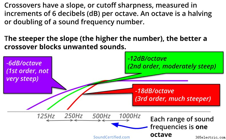
エンジニアリングの世界ではデシベル (dB) を使用してスピーカー出力レベルまたはオーディオ クロスオーバー信号値を測定します。これはどちらも非線形であるためです。これは、オーディオの場合、10 の累乗に基づいて増減することを意味します (別名、対数です)。
前の負の記号は削減を示し、前の正の記号またはなしは増加を示します。
例: -6dB/オクターブのスロープを持つクロスオーバーは、カットオフ周波数を超えると、オクターブごとに 6 dB 減少する出力を持ちます (周波数の半分または 2 倍:400Hz、800Hz、1,600 Hz など)。
スピーカーのクロスオーバー ポイントとは?
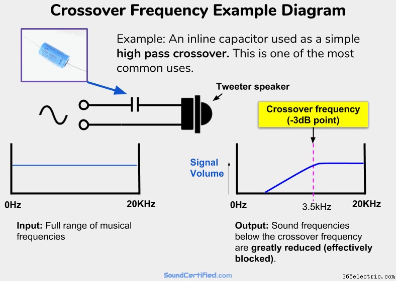
スピーカーのクロスオーバー ポイントは通常、クロスオーバーと呼ばれます 頻度 「Fc」と表記されることもあります 」は「カットオフ周波数」を表します。 A スピーカー クロスオーバー ポイント はカットオフです 頻度 この周波数を超えると、スピーカーに到達するオーディオ周波数が大幅に減少し、スピーカーを効果的にブロックします。
技術的には、クロスオーバーの出力が 3dB 損失するポイントに基づいています。 電力用語では、-3dB ポイントは 頻度 で スピーカー は 1/2 に減少します。
クロスオーバー周波数 (-3dB ポイント) をさらに超えると、出力はさらに減少し、実質的にゼロになります。たとえば、カットオフが 1kHz の -6dB/オクターブ ツイーター クロスオーバーの場合:
- ツイーターの出力は 1kHz で -3dB です。
- 1 オクターブ離れた場所 (500Hz) で、出力は -6dB になります。
- さらに離れた周波数では、出力はほぼ 0 デシベルになります。
クロスオーバー デザイン タイプと関連する詳細の選択
クロスオーバー タイプとスロープの選択
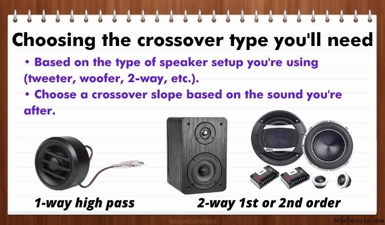
お使いのスピーカー システムに基づいて、使用する最適なクロスオーバー スロープとクロスオーバー オーダー タイプの推奨事項を次に示します。これらは一般的に最も人気があり、ほとんどの場合に機能することに注意してください。
- 単純なツイーター クロスオーバー (ハイパス、トレブルまたは「ハイ」用) またはウーファーまたはミッドレンジ スピーカー クロスオーバー (低周波信号を通過させるため) の場合、1 次、6dB/オクターブ タイプ通常は問題ありません。不要な周波数をさらにシャープに除去したい場合は、2 次の 12dB/オクターブ設計もオプションです。
- 双方向の場合 スピーカー システム a 2次 Linkwitz-Riley は、多くの場合、音質とパフォーマンスの最適な妥協点です。 1 次はシンプルで簡単に作成できますが、特別な理由がない限り理想的ではありません。もう 1 つの利点は、正しく使用すると同相のスピーカー出力が得られることです (これについては後で説明します)。
- 3 方向設計の場合は、2 番目のタイプで問題なく、フェーズの問題や発生する可能性のあるその他の複雑さの問題も回避できます。
Linkwitz-Riley vs Butterworth およびその他の 2 次クロスオーバー タイプ
Linkwitz-Riley 設計は、さまざまな理由で最も一般的に使用されている設計の 1 つです。主な理由は、ウーファーとツイーターのクロスオーバー ポイント出力がオーバーラップするフラットなレスポンスです。 Butterworth、Chebychev、Bessel などの他の設計では、特定の設計目標に役立つさまざまな量のゲインが提供されますが、同じ周波数応答は提供されません。
リンクウィッツ ライリー (L-R) クロスオーバー は を構築するための優れた選択肢です。 標準 スピーカー デザイン オクターブあたり -12dB のスロープと優れた (フラットな) 出力を備えています。
2 次 L-R クロスオーバーは、合計するとフラットな大きさになるオールパス構成です…フラットな振幅応答、オフセットに対する感度の低さ、および帯域内ドライバーの共振により、L-R はメーカーの間で人気のある選択肢となっています.Vance Dickason, The Speaker Design Cookbook (第 7 版)
別のトピックですが、L-R クロスオーバーはスピーカー ドライバーの共振の影響を受けないという別の利点もあります。詳細に興味がある場合は、Vance Dickason の The Loudspeaker Design Cookbook を手に入れることをお勧めします。 .
クロスオーバー周波数の値を見つける方法
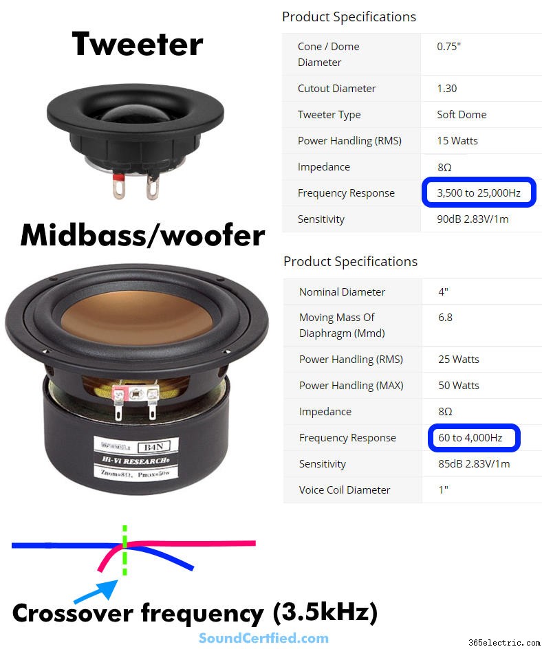
良いニュースは、独自の設計と構築を行うために選択すべきクロスオーバー周波数を判断する方法がいくつかあるということです:
- メーカーの推奨事項
- 仕様が提供されている場合のスピーカーの周波数応答。 (残念ながら、いつでも利用できるわけではありません!)
- スピーカーの種類とサイズに基づく一般的な経験則 (ツイーターとウーファー、小さなコーンと大きなコーン スピーカーなど)。
最良の結果を得るには、おそらく上記のものを 2 つ以上使用することになるでしょう。
注: 3 ウェイ スピーカーについても、少し特殊なケースであるため、個別に説明します。それについては以下を参照してください。
1.メーカーの推奨事項

運が良ければ、スピーカー会社が使用に適した周波数範囲を提供しているかもしれません。上の写真の例では、クロスオーバー周波数を少なくとも 3.5kHz に設定しますが、これはたまたま非常に一般的なものです。
2.ドライバーの周波数応答チャートまたは仕様
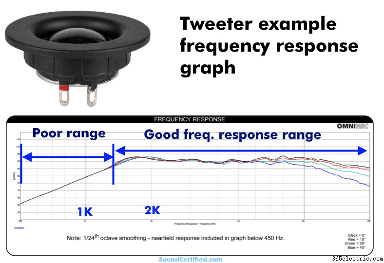
使用したいスピーカーの周波数応答グラフを幸運にも入手できた場合は、出力が不十分な領域を確認し、これをガイドとして使用できます。 .これらは避けるべき領域です。
そうするには、この範囲から離れたクロスオーバー周波数を選択します。 2 ウェイまたは 3 ウェイのセットアップを使用する場合、これは理想的には、他のドライバーまたはドライバーも同様にサウンドを生成できるポイントである必要があります。アイデアは、両方がそのポイントまで、出力のギャップまたは大幅に弱い範囲なしでサウンドを生成できる「中間点」を見つけることです.
上の例から、表示されているツイーターが 2 キロヘルツ (2kHz) 未満のどこかまで良好な出力を持っていることがわかります。少なくとも 2kHz 以上のクロスオーバー周波数を選択する必要があることがわかっています。
3.スピーカーのサイズとタイプ
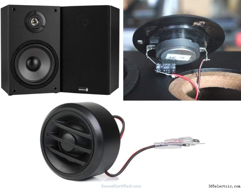
スピーカー ドライバーのサイズに基づいて必要なカットオフを選択し、次の経験則に従って入力すると便利です:
- ツイーターは、多くの場合、低音域または中音域を処理できない小さなドライバーを使用します。ほとんどの場合、約 3kHz 以上の音を生成できるため、通常は 3kHz または 3.5kHz のハイパス カットオフ周波数が最適です。
- 2 ウェイ設計で使用されるミッドレンジ スピーカーは、通常、約 3kHz ~ 3.5kHz まで良好です。 [3 ウェイ設計のミッドレンジ ドライバーについては、以下のメモを参照してください。]
- ミッドバスまたはミッドレンジの周波数を生成するウーファーには、多くの場合、120 ~ 250 Hz 程度のローパスが必要です。
- サブウーファーは、非常に限られた低域以外ではうまく機能しないため、多くの場合、80 ~ 100 Hz が最適です。場合によっては 120Hz も適用できます。
3 ウェイ クロスオーバー周波数に関する注意事項
そうは思えないかもしれませんが、3 ウェイ クロスオーバーは 2 ウェイ デザインの単純な拡張ではありません。この場合のアイデアは、ハイパス周波数とローパス周波数の間の広い周波数範囲を持つオールパス クロスオーバー (APC) 設計を使用することです。
これは、互いに近すぎると望ましくない相互作用が発生する可能性があるためです。以下の表またはハイパス カットオフの比率 (Fh) に基づくこの一般的なルールを使用できます。 ) とローパス カットオフ (Fl ):
良い 3 方向 クロスオーバー 比率: Fh/Fl =8 以上。
使用する優れた 3 ウェイ クロスオーバー周波数は次のとおりです。
- 3kHz/375Hz
- 5kHz/625Hz
- 6kHz/750Hz
上記の 1:8 の比率を使用するには、上の周波数を選択し、8 で割って 2 番目の周波数を取得します。同様に、より低い周波数を選択して 8 を掛けると、適切な上限カットオフ周波数を得ることができます。
3 ウェイ設計には、dB レベルが高いまたは低い中域出力があることに注意してください。この場合、3 ウェイ設計はツイーターとウーファーの出力に比べて 2.45 dB のゲインを持ちますが、これはかなり小さいものです。
一般的に言えば、2 つのクロスポイントが離れているほど、ドライバーの組み合わせレスポンスが良くなります (3 オクターブが良い出発点です)。
理想的な 3 オクターブよりも近いクロスポイントは、複雑で望ましくない干渉パターンに悩まされます.Vance Dickason
クロスオーバー回路の設計と部品値の検索
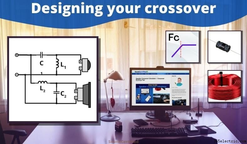
以下を取得したら:
- 必要なクロスオーバー タイプ
- クロスオーバー周波数。
- スピーカーとそのインピーダンス (スピーカーのオーム定格)。
…仕事に取り掛かることができます!幸いなことに、それほど難しくはありません。必要でない限り、自分で計算する必要はありません。 私の を使用できます スピーカー クロスオーバー 電卓 必要なパーツ値を提供します。
続きを読む »
クロスオーバー計算機の使用
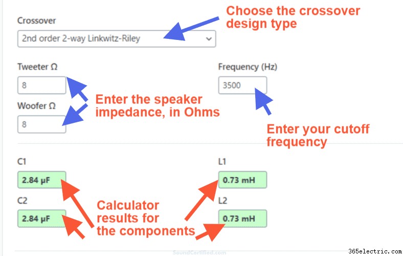
かなり自明ですが、計算機のページに説明があるので心配する必要はありません。値と選択肢を入力してください:
- クロスオーバー タイプ (明確にするために図が表示されます)。
- 使用されるスピーカーのインピーダンス
- 必要に応じたクロスオーバー周波数。
値を書き留めるか、下の回路図または見つけられる他の場所に保存してください。
DIAGRAMS – 印刷して使用するクロスオーバー ネットワークの図
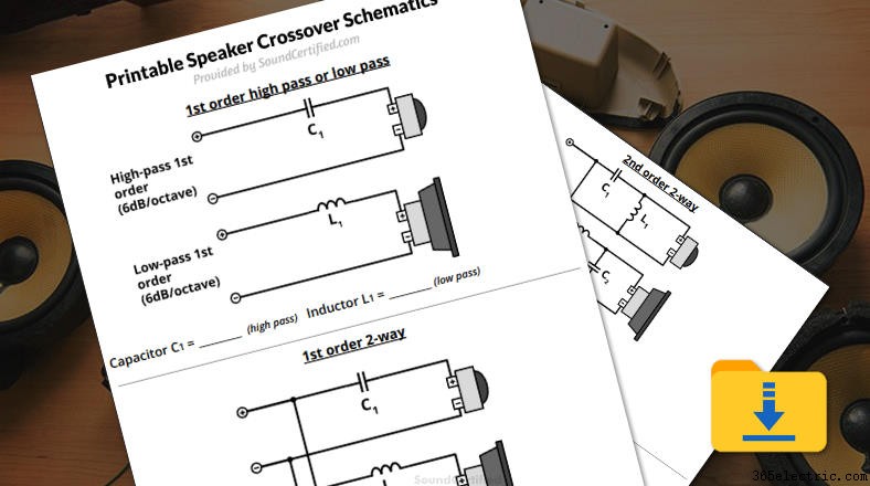
DIY クロスオーバーを構築するために提供されているクロスオーバーの回路図を表示または印刷するには、ここをクリックしてください。必要に応じて、計算した部品の値を書き留めるためのスペースがプリントアウトに提供されます。
パーツをまとめる
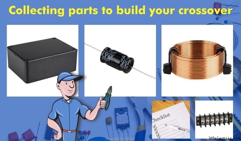
クロスオーバー コンポーネントの購入
最低限、次のタイプのクロスオーバー コンポーネントが必要です:
- 十分な電圧定格を持つ電解無極性 (バイポーラ) コンデンサ。これは通常、約 48V 以上の定格です。
- 空芯インダクタ。フェライト ボビン (フェライト コア) タイプも問題ありませんが、必須ではありません。
コンデンサはファラッドと呼ばれる単位で評価され、通常は「マイクロファラッド」で販売されます。また、ギリシャ記号 Mu (μF、ファラッドの 1/1,000,000) または小さな「 u」(uF)。インダクタはヘンリーで測定され、通常は「mH」と書かれたミリヘンリー (ヘンリーの 1/1,000) で販売されます。
バイポーラ コンデンサと分極コンデンサ
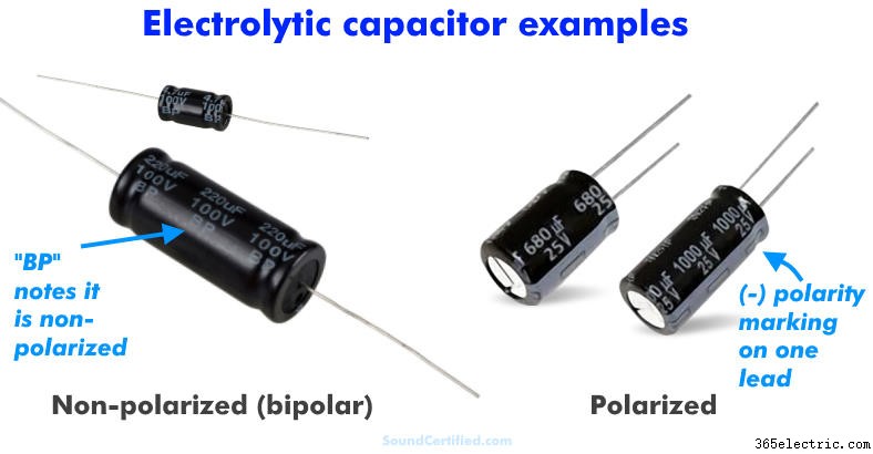
有極コンデンサーが最も一般的なタイプですが、オーディオ用途には使用できません。無極タイプを使用する必要があります。 その理由は、1) 反転する交流 (AC) 電圧を処理できない、2) 音が歪んだり、故障したりする可能性があるためです。無極性コンデンサーにより、電気的な音楽信号が正常に通過します。
バイポーラ (「BP」、無極性) コンデンサは通常そのようにマークされていますが、有極性タイプは片面にマイナス接続を示すストライプが付いています。
コンデンサの定格電圧
コンデンサは、最大定格を超える印加電圧を処理できません。経験則としては 48V 以上が適切ですが、アンプの RMS 電力定格が次のようにわかっている場合は、オームの法則を使用して最小値を自分で計算できます。
V (ボルト) =平方根 (電力 x スピーカーのオーム)
たとえば、チャンネルあたり 50 W のアンプから 8 オームのスピーカーへ出力電圧はおよそ平方根 (50 x 8) =20V になります。 より高い電圧定格は問題ありませんが、20V を下回ることは望ましくありません。見つかった次の定格以上の部品を使用します。
パーツ値の許容範囲 (「完璧な」値を探してはいけない理由)
電解コンデンサと空芯インダクタの公差は、表示値の約プラスマイナス 20% (+/-20%) です。 More expensive parts may have 10% or lower tolerance which is nice but not really necessary.
I say this to help get the point across that:
- No capacitor or inductor will have a perfect value – they vary slightly from their rated value.
- You don’t need an exact value, but rather the goal is to get it pretty close to the value you need.
- Inductors, capacitors, and resistors are sold in standardized values and you’ll almost never find the EXACT value. In many cases it’s not stocked by a supplier and not worth the time trying to search and search for it.
For example, a capacitor labeled as 4.7 uF (4.7 microFarad) may have an actual of around 3.76 to 5.64 uF when measured with test equipment. (It’ll probably be around 4 to 5uF but you see what I mean). The same is true for inductors too.
In that case, you’d buy a 4.7uF one if it’s reasonably easy to get but if not, the good news is there’s another way.
TIP:How to get the part values you need if you can’t find them
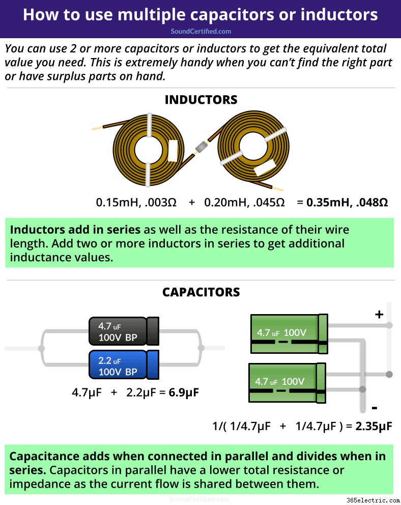
There’s a simple way to handle not finding the exact part values you need. The trick is to use multiple crossover components in such a way that they add up close to what you’re after.
- Inductance adds when they’re connected in series and divides when wire in parallel.
- Capacitance adds (sums) when they’re wired in parallel. The total capacitance divides when connected in series.
This means you can use spare parts or buy other parts of different values that are available to accomplish the same thing!
Miscellaneous parts you’ll need
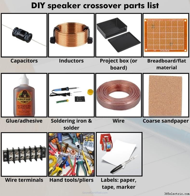
I can’t recommend enough being prepared. Here’s a general list of what you’ll need to build and encase your passive speaker crossovers:
- Project enclosure (if not being mounted directly inside a speaker cabinet), ideally made of ABS plastic.
- [Optional] Breadboard or other flat material for a mounting surface.
- Speaker wire or miscellaneous wire for connecting the components to each other and wire terminals.
- Sandpaper or metal file to remove insulating enamel from inductor wire ends.
- Wire terminals:I use a dual row inline wire terminal strip as they’re relatively easy to get, not expensive, and can be mounted with screws.
- Adhesive to mount your parts:General adhesive, silicone-based adhesive, or a hot glue stick and a hot glue gun (although not recommended for hot areas).
- [Optional] Labels:Clear Scotch tape or shipping tape and white paper + permanent marker or black &white printer.
- Typical hand tools:cutting pliers or needle nose pliers, Philips screwdriver, and others as needed.
TIP: When shopping for a project enclosure, be aware that the screw thread columns take up some of the internal space. You may need to buy a slightly larger size if the space is too tight.
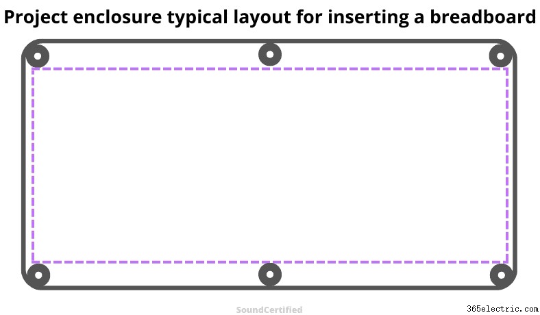
I recommend always checking how much room you’ll need based on the size of your capacitors and inductors.
DIAGRAM – How to build your speaker crossover

Prepare the crossover circuit &components for assembly
Once you’ve got your parts and the schematic it’s time to jump right in! To build your crossovers, I recommend doing the following:
- Place the capacitors and inductors in the project box in order to figure out the best placement before you start building. Sometimes space is tight and you don’t want problems when you’re already in the middle of building the crossover network circuitry.
- If you’re using a mounting board or perfboard, etc., measure between the cover screw columns. This is important because many plastic project enclosures have screw bases that take up space on the inside. Cut your board as needed to fit this area.
- Although it can be possible to find a single-row wire terminal strip they’re hard to get. I recommend using a dual row strip as they’re affordable and much easier to find.
- With the top on the box, place the terminal strip slightly below the top to leave enough room for wiring to exit below the cover when it’s on. Using a permanent marker or knife, mark the area above it and cut that section of plastic out.
Mounting &connecting your components
- I recommend using a non-permanent adhesive like hot glue and a hot glue gun, silicone sealant, contact adhesive, Gorilla Glue, etc. to mount the parts. This way you can remove them later if you need to modify the design or reuse parts.
- For warmer temperatures hot glue really isn’t so great. Hot glue can become detached from the mounting surface in warm temperatures and doesn’t stick well to smooth surfaces like ABS plastic, either. For that reason I don’t recommend it in most cases.
- Inductors use magnet type wire which has an enamel insulator you’ll need to remove with coarse sandpaper, a file, or Dremel tool. In order to solder the wire ends, you’ll need to expose the wire surface and provide a good clean contact area.
- You can use spare speaker wire or miscellaneous stranded hookup wire to connect the components together.
You can also use crimp connectors instead of a soldering iron and solder, although I personally recommend soldering for the best connection possible.
Going by the crossover schematic, connect each section to the next and double-check your work.
Proper placement of inductors
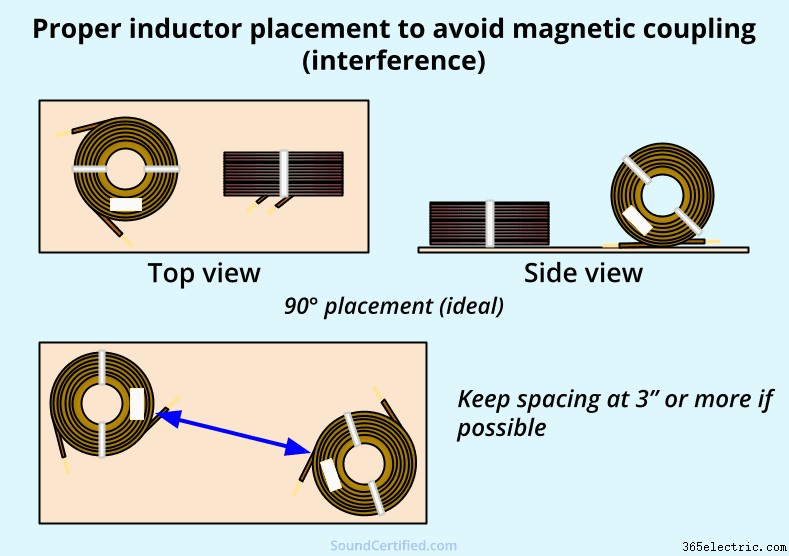
Inductors, as you may already know, work by increasing the magnetic field strength using loops of wire. Because of this it’s possible for one to cause magnetic coupling (interference) which can induce a signal or distortion in another.
To avoid this, if at all possible mount them at a 90° difference as shown in the diagram above or a minimum of about 3 inches. I begin by placing them at opposite corners of the box when building mine.
Putting it in a project enclosure
Once you’ve got the crossover circuit built, place the whole assembly in the box and use a bit of adhesive to hold it inside if you like (optional). Connect the amp side wiring, negative side wiring, and speaker output wires to the terminal strip on the top row.
This will leave the bottom row free for speaker connections.
Speaker terminals and tweeter polarity
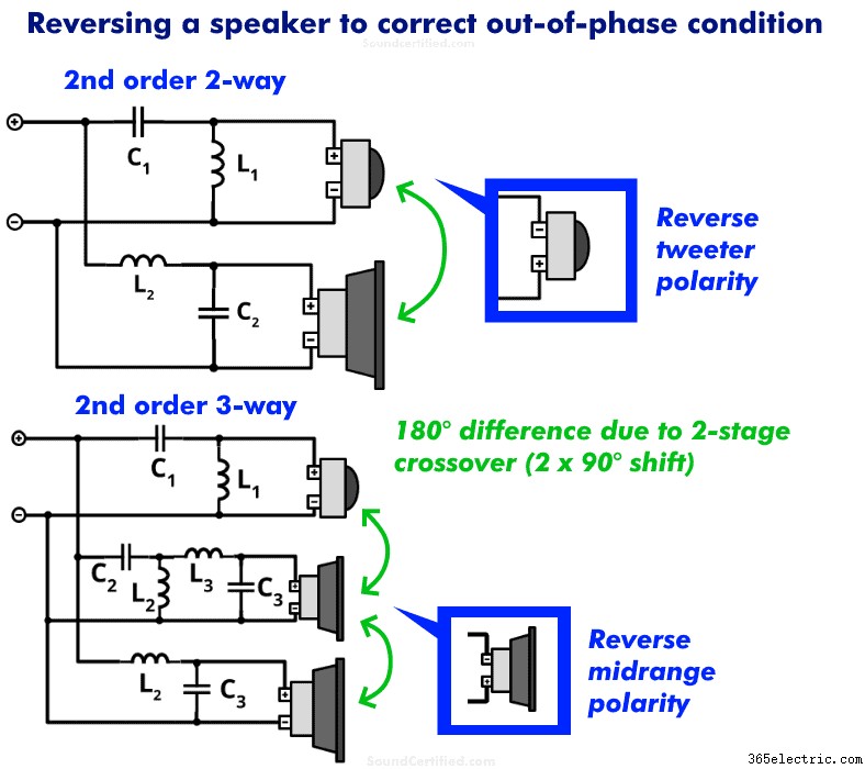
Second order networks have an output signal phase difference of 180 degrees. Fortunately, unlike odd-order designs (1st order or 3rd order) we can get a perfectly in phase (0° difference) sound output easily.
To do this with second order networks:
- 2-way speaker systems: reverse the tweeter output crossover connections at the wire terminals and connect the tweeter like you normally would. This puts the tweeter back in phase with the woofer / bass driver.
- 3-way speaker systems: reverse the midrange polarity to the wire terminals for the crossover.
[Optional] Adding speaker wiring labels
Want to add an extra touch? You can easily make your own labels for your speaker and amplifier input connections. Personally, I recommend the following steps:
- Using copier or printer paper, write your connection label notes using a Sharpie permanent marker. Optionally you can print using a black and white printer (although it’s harder to get text lined up perfectly).
- Cut out the labels using scissors.
- Using clear tape such as large shipping tape, place the tape over the label and trim with scissors if needed.
- Apply the label to the project box.
Example of a finished DIY speaker crossover
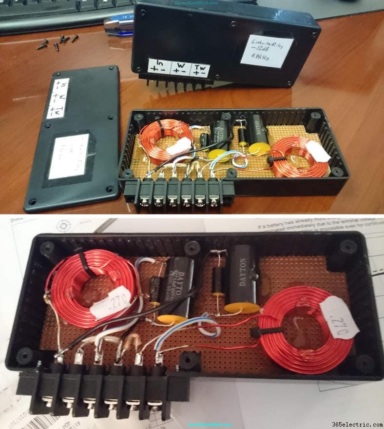
Here’s an example of my own – one of my first DIY crossovers projects I built myself. As you can see it doesn’t have to be perfect – but does need to be well-connected, use the right parts, and be put together in a way that’s practical for everyday use.
Note that if you’re installing yours directly in a speaker enclosure it’s not necessary to use a project box, but the rest of the steps should still apply.
Hopefully you’ve found my guide helpful. Here’s to enjoying good sound the way you like it – and proving you can do it yourself!
More helpful crossover resources you’ll enjoy
- Check out my L-pad, speaker Ohms, and other audio calculators here.
- Learn more details about what capacitors and inductors do in a crossover.
- Here’s a lot more helpful info about what a crossover frequency is.
- What more knowledge? Here I cover how to determine the speaker crossover frequency.
- The crossover frequency Fc, slopes, and why they matter.
- Find out a good crossover frequency for car or home audio.
